

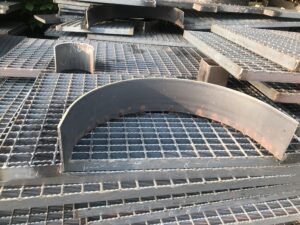
A steel grating stair tread drawing must describe its interface with the stair structure as well as the grating surface. Overall size alone does not define the end connections or the intended installed position.
Label the tread dimensions
Show the specified width, depth and bar direction using a clear drawing convention. Identify the reference faces used for dimensions and distinguish the tread dimensions from the distance between supports. Record the required material, surface and finish.
Detail the end connections
- End plate or other connection arrangement.
- Hole sizes and locations from stated datums.
- Any slot or adjustment detail approved by the project.
- Specified connection components and responsibility for supply.
- The intended orientation in the stair assembly.
Identify the leading-edge detail
Specify the nosing or leading-edge arrangement shown in the design. Coordinate it with the tread depth, connection geometry and adjacent stair details. Ask for clarification if the product drawing and stair drawing use different reference points.
Confirm the acceptance basis
The stair designer should establish the applicable dimensional and performance requirements. Keep those requirements with the approved tread drawing rather than relying on a generic product label.
Use the replacement-tread measurement guide for existing stairs or the tread quotation schedule for a new order. See steel grating stair tread options.